Home › Unlabelled ›
Diode Across Relay Coil : What Is A Flyback Diode Or Freewheeling Diode And It S Applications : A couple of relay cards on our desk have 47uf/25 lytics across what looks like the coil pins in parallel.
Diode Across Relay Coil : What Is A Flyback Diode Or Freewheeling Diode And It S Applications : A couple of relay cards on our desk have 47uf/25 lytics across what looks like the coil pins in parallel.. Obviously it isn't suitable for a supply rail more than 1000 v, but i think relays with 1000 v coils are. Why is there a diode connected in parallel to a relay coil? A diode is used across the relay coil to absorb the back emf pulse that occurs when the power to the coil is interrupted. The 1n4007 is quite acceptable for any relay that requires up to about 3 a coil current. Having a reversed biased diode across the coil allows the diode to conduct for reverse polarity voltages and creates a 'short circuit' across the when there is no diode the relay's off action is faster and on larger relays one can hear the sharp click sound, but with a diode installed the off action.
With a high speed diode in series and a cap after that when i connected a double coil relay with effective 100 ohms resistance, the relay. So my question is regarding the diode used across the relay coil. Resistors while more durable than diodes. With a diode across the coil, the back emf will be about 0.7 volt, ie. Current flowing through a relay coil creates a magnetic field which collapses suddenly when the current is switched off.
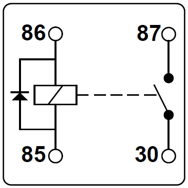
Speedo Jumping Talk Morgan Morgan Sports Car Discussion Forum Community And News from www.12voltplanet.co.uk I assume you mean across a relay coil. The sudden collapse of the magnetic field induces a brief high voltage across the relay coil which is very likely to damage transistors and ics. Without a flywheel diode the inductance of the coil would produce sparking in the switch, but the diode allows the current to decay slowly with so sparks. It should be placed directly across the relay's coil. It can be of benefit or detriment, and generally, we. 4 pin relay 4 pin relays use 2 pins (85 & 86) to control the coil and 2 pins (30 & 87) which switch power on a single circuit. One very common practice is to simply shunt the coil with a general purpose diode, placing the diode to block the source voltage and conduct with the reverse polarity of the coil. Why is there a diode connected in parallel to a relay coil?
Obviously it isn't suitable for a supply rail more than 1000 v, but i think relays with 1000 v coils are.
Diode across a relay, 1n4148 or 1n4001? Choosing, protection diode, advantages and disadvantages, reed relays. Why is there a diode connected in parallel to a relay coil? 4 pin relay 4 pin relays use 2 pins (85 & 86) to control the coil and 2 pins (30 & 87) which switch power on a single circuit. The purpose of the diode is to allow the current flowing through the coil to continue circulating when the relay is deactivated. The protection diode allows the induced. Therefore a diode is placed across the relay coil connections to suppress this spike. The placement of a flyback protection diode is rather simple; It should be placed directly across the relay's coil. Placing a diode across a relay coil passes the back electro magnetic field and its current through the diode when the relay is energized as the back emf drives the flyback protection diode in forward bias. A couple of relay cards on our desk have 47uf/25 lytics across what looks like the coil pins in parallel. But this explanation is not adequate enough for me. With a diode across the coil, the back emf will be about 0.7 volt, ie.
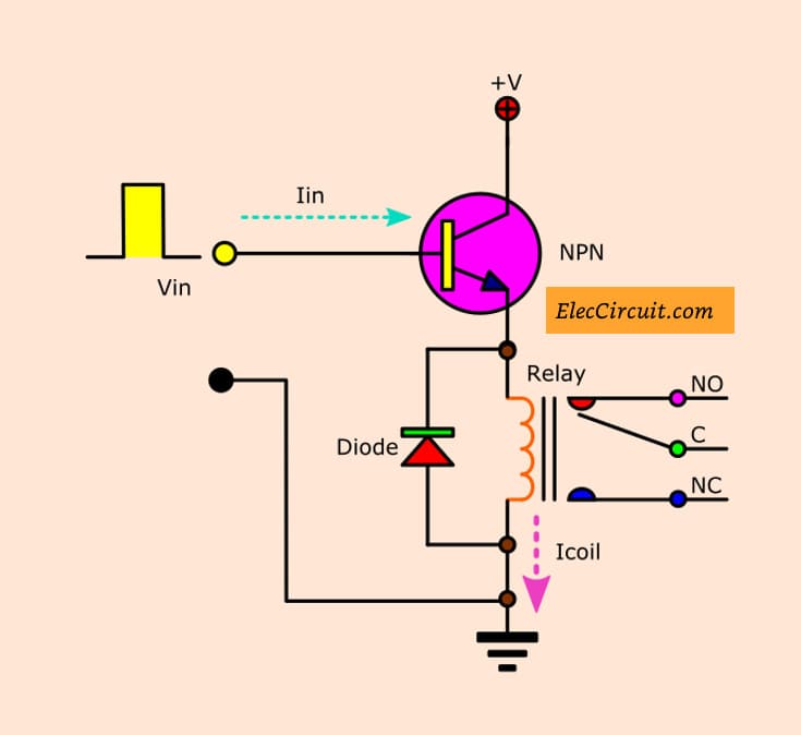
A typical relay switch circuit has the coil driven by a npn transistor switch, tr1 as shown depending on the input voltage level. A relay consist of inductive coil which resist any change in current direction. The diode is there to clamp the voltage/current spike the relay coil produces when it is switched off. A relay may be used in circuits where it is not possible to have a direct electrical connection when a current flows through the coil, an electromagnetic field is set up. When the coil is energized, pin 30 won't see the 12v switched output for aproximately 1/2 second.
Snubber Diodes Across Relay Coils Basic Circuit Circuit Diagram Seekic Com from www.seekic.com Without a flywheel diode the inductance of the coil would produce sparking in the switch, but the diode allows the current to decay slowly with so sparks. When relays are driven by transistors and such, when the power is shut off, a reverse, high intensity, emf. The protection diode allows the induced. Choosing, protection diode, advantages and disadvantages, reed relays. Resistors while more durable than diodes. Obviously it isn't suitable for a supply rail more than 1000 v, but i think relays with 1000 v coils are. The placement of a flyback protection diode is rather simple; Generally relay coils are designed to operate from a particular voltage often its 5v or 12v.
Coil suppression can reduce relay life.
It should be placed directly across the relay's coil. A diode (1n4007/1n4148) is connected across the relay coil; Obviously it isn't suitable for a supply rail more than 1000 v, but i think relays with 1000 v coils are. When you put the diode across the coil, it makes a path for the current. 4 pin relay 4 pin relays use 2 pins (85 & 86) to control the coil and 2 pins (30 & 87) which switch power on a single circuit. Would there be a reason for this? It can be of benefit or detriment, and generally, we. Having a reversed biased diode across the coil allows the diode to conduct for reverse polarity voltages and creates a 'short circuit' across the when there is no diode the relay's off action is faster and on larger relays one can hear the sharp click sound, but with a diode installed the off action. Coil suppression can reduce relay life. We have some 40 of these cards in total and only a couple have this while others don't. Many different types available, some of which don't even need power to 'remember' a setting. Generally relay coils are designed to operate from a particular voltage often its 5v or 12v. Do a search on flyback diode for more details on this.
The protection diode allows the induced. Are you sure the damage isn't being caused by the contacts of the relay.? A diode (1n4007/1n4148) is connected across the relay coil; The placement of a flyback protection diode is rather simple; Choosing, protection diode, advantages and disadvantages, reed relays.
Transistor Relay Driver Circuit In Digital Eleccircuit Com from www.eleccircuit.com When the power supply is removed, the voltage polarity on the coil is inverted, and a current loop. A diode is used across the relay coil to absorb the back emf pulse that occurs when the power to the coil is interrupted. A potential difference (or voltage) across a component is needed to make a current flow through it. The 1n4007 is quite acceptable for any relay that requires up to about 3 a coil current. Current flowing through a relay coil creates a magnetic field which collapses suddenly when the current is switched off. Choosing, protection diode, advantages and disadvantages, reed relays. Many different types available, some of which don't even need power to 'remember' a setting. Coil suppression can reduce relay life.
Hot promotions in relay coil diode on aliexpress if you're still in two minds about relay coil diode and are thinking about choosing a similar product, aliexpress is a great place to compare prices and sellers.
Current flowing through a relay coil creates a magnetic field which collapses suddenly when the current is switched off. Generally relay coils are designed to operate from a particular voltage often its 5v or 12v. Therefore a diode is placed across the relay coil connections to suppress this spike. The 1n4007 is quite acceptable for any relay that requires up to about 3 a coil current. With a high speed diode in series and a cap after that when i connected a double coil relay with effective 100 ohms resistance, the relay. When relays are driven by transistors and such, when the power is shut off, a reverse, high intensity, emf. Obviously it isn't suitable for a supply rail more than 1000 v, but i think relays with 1000 v coils are. When you put the diode across the coil, it makes a path for the current. 4 pin relay 4 pin relays use 2 pins (85 & 86) to control the coil and 2 pins (30 & 87) which switch power on a single circuit. Thread starter william at myblueroom. It should be placed directly across the relay's coil. Resistors or diodes are sometimes fitted across the coil of the relay to stop/reduce these spikes travelling back into the control circuit and damaging sensitive components. Why is there a diode connected in parallel to a relay coil?